For the input device week i chose to work with a light sensor since i need it for my final project. A light sensor will generate the output device a dc motor and will give power to a conductive thread the same time. After watching Neil's suggestions this week i decided to create a board inspired by the board that he proposed but the same time to enrich it with more pins since i would like to connect it with more boards and functions in the future.
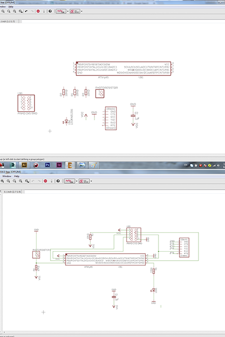
After adding in the schematic all the components that was suggested i added more pins and i connected them with the microcontroller.I used the Attiny 45 because of the high memory and speed.The components that were used were the ones suggested by fab academy. Unfortunatelly, because of the small size of the attiny 45 its was very hard to create the circuit.
The first board was a testing one in order to test if the rolland milling mashine could mill small paths through the tiny attiny 45. The trial was not suggesful and i had to find another way to create the circuit.After a lot of trial i changed into attiny 44 (smaller size) and with the help of some zero resistants -bridges i managed to have a proper board design.
Finally, the last version of the board was changed a lot after i got inspiration from another fab academy student , Anke Brocker. I found her approach the right one for me since she used female pins, and she drilled the board so they can be connected from the surface under. I found this way the most appropriate way for my circuit and more easier to solder them after.
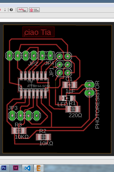
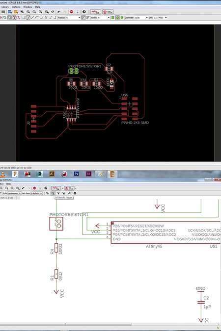
One of the problems that i have with the eagle software is that the free version that i use have a bug which causes a lot of problems. One of the problems (apart from insufficient labeling) is the wrong way to create paths so in the end after a lot of hours trying to solve the puzzle i decided to import the png file in illustrator and add the right bridges there.
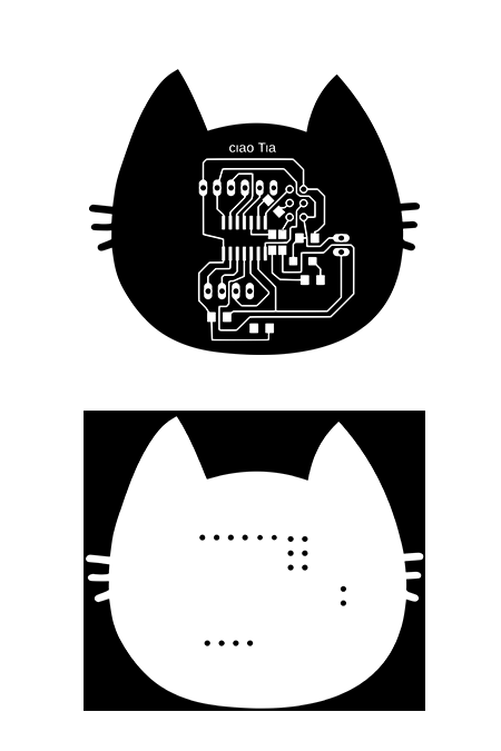
The png file was imported in illustrator (after the right preparation that is documented in the electronics production week) and the bridges/ zero resistors were added. A more personal style was added as an outline ;-) and the holes were adding too in the outline sketch. After the right preparation the file was exported in png with 1000 ppi and was ready to be inserted in fab modules.
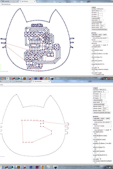
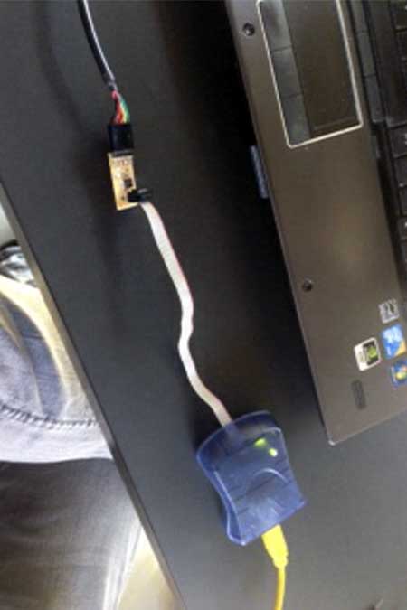
This step is documemted in the electronic productions week.The mashine taht was used was a rolland milling mashine.
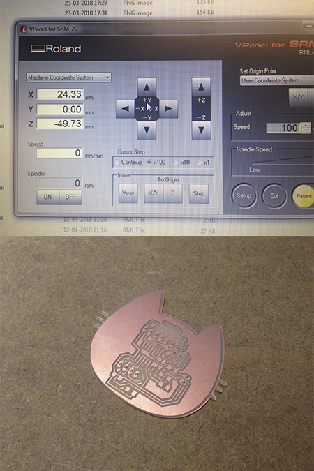
This step is documented in the electronic productions week.The mashine that was used was a rolland milling mashine and the right bits were an 1/64 inc bit for engraving the traces and a 1/32 inch bit for the outline cutting.
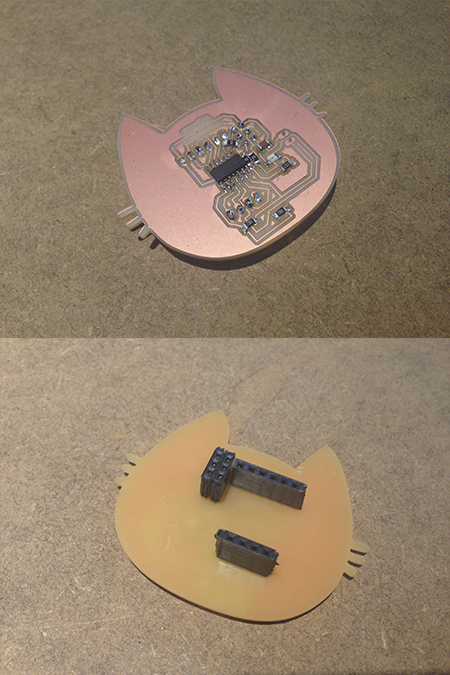
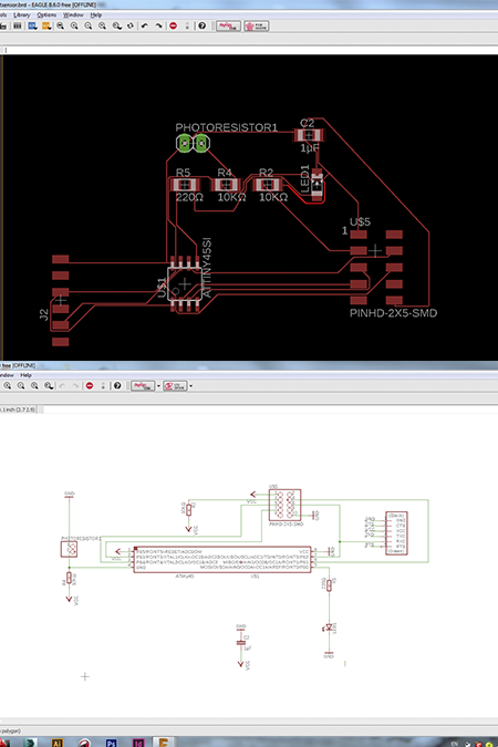
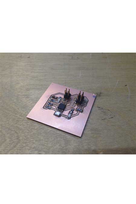
After milling I soldered all the components to my board. The components are: an Attiny 45,, a Photeresistor, 10mikroF SMD Capacitor, 2 x 10kΩ SMD Resistor,220Ω SMD Resistor, red SMD LED, 2 female Pinheader, 4 female Pinheader , 6 female Pinheader, 3 zero resistors.
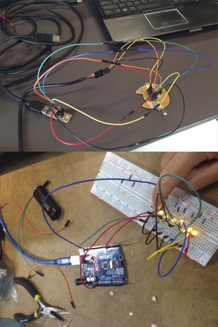
After a lot of times trying with my instructor to make the photosensor to work i decided to change my tactics and methodology.While coding the mistake i was always receiving was that there was a problem with the connections while the board was recognised from my isp. So, i decided to reproduce the photosensor circuit and a nes button input with arduino.In both cases the circuits worked and i was ready to design the files in eagle, mill them and connect them to my fabduino.In order to check also the result i combined it with an output of seven leds!!They worked both with the button input as well as with the photosensor output.
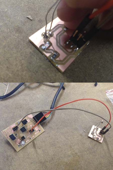
For the next step i designed in eagle the photosensor circuit exactly the way that i designed in in arduino. After i milled it and in order to check it i connected it first with the arduino and after with my fabduino by changing the right pins in my arduino code. It worked!!!!!
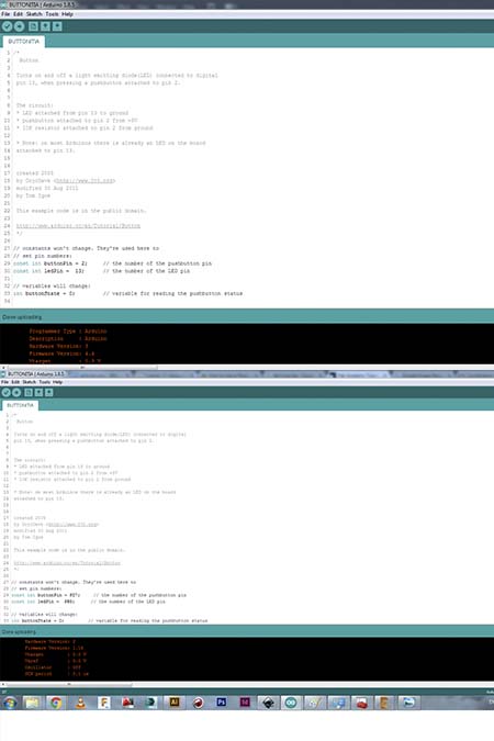
The arduino codes of the photosensor and of the button where succesful.
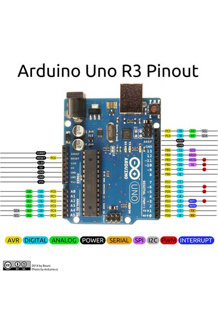
The most important thing from connecting first the board to the arduino and after to my fabduino was to translate the pins in the code. The arduino uno has different pins from my fabduino and the sketch above helped me a lot to recreate the right pins.
The next step was to create an independent photoresistor like the one in Neil's example. I used a microcontroller attiny 45 and this is the final protoype fro my final project. The darlighton photoresistor works much better and it it far more sensitive to light changes than the one form the arduino kit that i used in my first protoype.In theVIDEO is visible how sensitive it is and how easy to use.
After testing the phototransistor of Neil I worked on an upgraded version thinking of my final project. The idea is to have the photodetector triggering a signal (when there is no enough light) to send it to another board where my RGB led connected to the optic fiber will turn on. I decided to have the ATtiny45 of the input board detect if there is not enough light and in case send a signal out. I also want to add a small blue led that turns on when this happens and a red led when the power is on (there is not such a thing as too many leds! :D ).
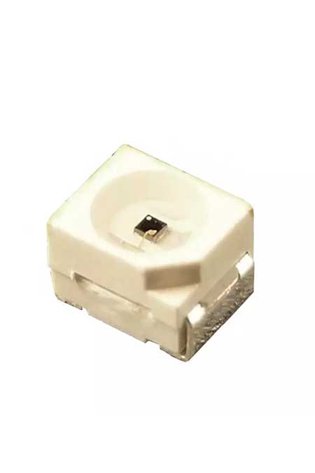
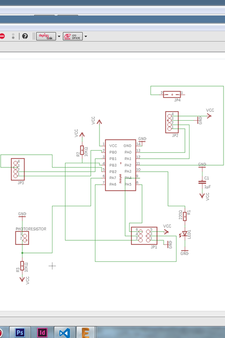
I need the following components: Phototransistor, we have the PHOTODARLINGTON NPN CLR PLCC-2 A 10KΩ resistor for the photodarlington The ATtiny45 The pull-up 10KΩ resistor for the RESET pin and the 10 uF capacitor for the bypass The 6pin connector for the ISP (so far same as the Neil board) A 4 pin connector for power and I/O (I am gonna use I2C) A blue and a red LED with their 500Ω and 1kΩ resistors I will also need a 0Ω resistor (a bridge) to be able to route all path on one side of the board
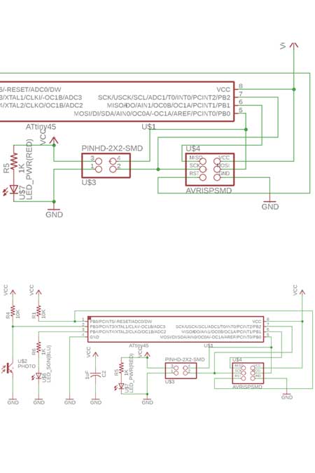
I started with the phototransistor, connected to PB3 of AT45 and with the 10ΩK resistor to VCC (same as last time I added the blue led on PB4 so that when the signal is sent I can check it from here (great for debugging!!!) and grounded the AT45 Then I moved to the connection side. The 6 pins for the ISP and the 4 pins for I2C including the power source of the board to which I added a red led. (spoiler alert: to this side I will have later on to add a 0 ohm resistor to be able to route the paths) Finally added the pull-up resistor on the RESET and the bypass capacitor:
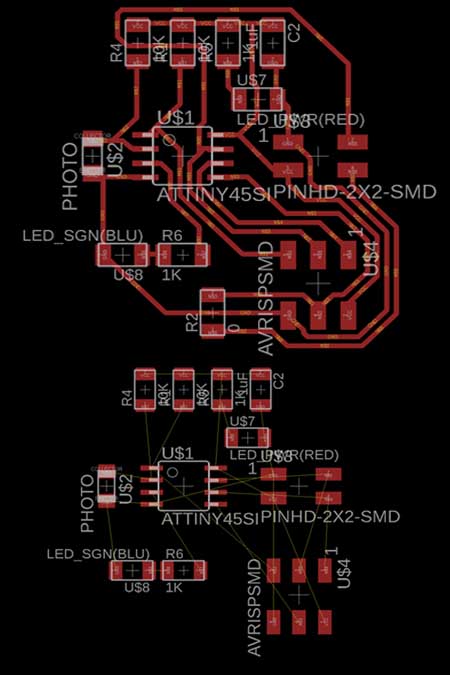
I started with the big components first: placing the AT45, the two connector blocks and the phototransistor, rotating them so that the airlines were intersecting as little as possible, then I placed the small components (resistors, capacitor and leds) around them The auto routing was not very successful, I ended up doing most of the job manually, but no matter how I rotated or moved the component I always had at least 1 airline crossing others… I surrendered to the idea of using a bridge, the best one seemed to be the MOSI. Finally I ended up with a nice clean layout…
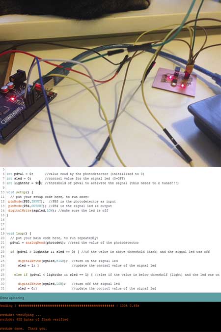
After having soldered my board and tested it with the multimeter everything was succesful and i started to modify the code in Arduino IDE. I used exactly the same code that i used to program my photosensor connected with my faduino but of course in this case i had to change the pins according to my board and the same time to set new pins since i added two more leds. By using the if and else command i managed to program the leds to light according to the value of the photoresistor. In the end ,it was very tricky to set the right parameters for the phototransistor since the light is always in transformation. I realised that the best range is around 400-900 but this something that i will keep reprogramming according to the room that the phototrasistor is every time.
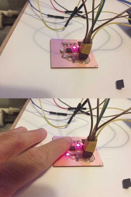
And here it is!!!!!!Twp pictures before and after the shade. But since the pictures do not communicate all the joy that i took from this a VIDEO is always a good idea.
The conclusion of this week is that the input devices should be studied together with the ouput device week in order to perceive a complete idea.